DC Charging Philosophy |
Scroll down (or click) to read:
• Actual Charging Methodology • Idealized Charge Cycle • Charge Efficiency Factor (CEF) • Description of Alternator Output • Alternator Sizing, Extended Operation - Overloading • Remote Battery Charging • Number/Size of Batteries Required (Ah capacity) • Testing your Batteries Before we begin, an EXTREMELY IMPORTANT FUNDAMENTAL CONCEPT must be understood regarding battery charging! Regardless of how the battery bank receives its charge (Shore Power or an AC generator supplying ac voltage to a battery charger that then changes this ac voltage into dc voltage to be used for charging), DC Generator, DC Alternator, or even a DC Duo Charge, IT IS THE BATTERY BANK THAT DETERMINES and REGULATES THE CHARGING - IT IS NOT THE CHARGING SOURCE that determines the charging. In our discussions with the vast majority of the public, they think it works the other way. Unfortunately, this flawed foundation leads to many erroneous mistakes and decisions. |
Think of your stomach as the battery bank, your plate, arm & hand, and fork as the source & required parts needed to provide the charging amps, and lastly your
brain as the regulator. When your are very hungry (stomach telling brain - I must eat now and in "large" quantity). This is the first (bulk) stage of the charge
cycle. When you feel a little full, your brain will modify your actions and tell your arms to not send as much food into your mouth, but instead take smaller
portions. This is the second (acceptance) stage of the charge cycle. Eventually, you start to nibble. This is the third and last (float) stage of the charge
cycle. When you eventually stop eating, it is like turning off the regulator.
However, sometimes you may fail to turn off your body's regulator and keep nibbling (? Thanksgiving, parties, ...). This leads to you overeating and becoming stuffed. This happens to batteries also. This is why you should always turn off the charging input when a battery is 100 per cent full and do not stay in the float mode charging for extended or indefinite periods. During the entire evolution you do not eat at exactly the same rate in a linear motion. It is constantly being modified as your brain and stomach (battery & regulator work the same way) interact. This situation is displayed on a battery monitor as constantly changing numbers as the battery and regulator interact telling the charging source what to do (modify output). This varies widely depending on many parameters (battery bank size, age, and condition, amps available for charging, amps being consumed by items on, wire size, ...). There is no need to stare at a battery monitor every second, just observe the charging as it proceeds over time as conditions warrant or you desire - apx every 15-30-60 minutes. |
Assuming your boat is large enough (a relative term) to require extended DC capacity, the following discussion should answer most questions. The reasoning for
the approach below is to put to use the drive engine for charging ONLY when under load (such as motoring). The battery bank is to hold you over in between. This
will be calculated in step one.
You do not want to use your engine for charging at anchor or it will be the most expensive generator you purchase. Its life will be shortened immeasurably and cost much more on maintenance. Extended no load operation of a diesel engine will "glaze" the rings and unfortunately will cause oil blow by at some point. The exhaust system will also start sooting over. The tell-tale sign of this is that the engine exhaust will start to blacken. This is an often occurrence to overland trucks when their drivers pull off to sleep in their cab overs and leave the engine running as a normal practice (to run the A/C or heaters....). We have found that a lot of the cross-country truckers are adding small generators to their rigs to preclude this from happening. The key point to note is the no-load, extended period engine run time. An occasional or short period should not be a long term factor. For those vessels that do not have a generator installed (regardless of reason), a short term or VERY occasional way to charge at anchor is the following. Ensure your anchor is set properly and then engage your engine's propeller in reverse with a typical rpm range between 1,500 to 1,800. Combined with the added prop load, propulsion engine alternator charging will not cause engine damage, but has other associated deficiencies for another discussion. Remember, this is an occasional remedy! It should not be your standard routine for charging when on the hook. As we just discussed, if room allows, and more capacity is desired, a dedicated Generator is required. Preferably a ZRD DC Generator would be used instead of an AC Generator enabling minimal run times, low noise, and significant fuel savings. Click on Why choose a DC Generator over an AC Generator? to read the details. Everything may be run from with the house battery bank (an inverter will provide 120vac as needed) being the power source. The Generator only needs to be run when the battery bank needs to be recharged. A properly sized battery bank will provide all of the needed power to run all equipment, even appliances. Again, charging only takes place when the battery bank gets discharged to apx 12vdc. First, you need to calculate your demand for DC power (add up the max DC amps consumed between charge cycles). This amount needs to be doubled because you do not want to go below 50% on a regular basis or the battery life will degrade. When you are calculating, consider worst case, such as anchoring for extended periods. Experience and observation puts this number at 750Ah on the low side, 1000Ah as average and anything higher as great. If you are in a power vessel instead of sail that has high draw items, this will be even higher. You may be limited by the room on hand. 1000Ah takes 4 8D batteries. Second, now that you have the amount of DC amp hours required, double that number and divide the result by your charging sources capacity (standard alternator, "inverter", generator…) and you will have the approximate time needed to do the charging. With this in mind, it brings up whether your sources are adequate. This is usually the point, where one decides/figures that one does need that second High Output Alternator (See link on sizing). This is truly the best approach. Keep your standard low amperage alternator to charge your starting battery. Use the second High Output Alternator to charge the house bank. With the correct wiring and switches, there are backups. Also, this is the point where one may discover that one's desires or needs may be beyond the physical size and limitations produced by their vessel. In this situation, one has to accept these limitations and use the vessel with this in mind. Do not go beyond the limitations or comfort or safety will be compromised. The standard alternator or an upgrade to a ZRD 94amp (12vdc) High Output Alternator is your only smart, safe option. Unlike other vendors, we will let you know if you are close to this situation and recommend not purchasing a renovation and living within the vessel's limitations until you are ready for a vessel upsize that will allow your desires to be installed and met. Third, power drain. Calculations dictate that 2 HP is required for every 100 DC amps generated. The industry uses an efficiency factor of 50% (Our testing finds that most alternators are more efficient than 50%, but each should be verified for your use) for motors/generators. A ZRD High Output 220amp Alternator requires considerably less than others at full output, due to their design and manufacture. This should not be a problem for most inboards. We have installed them on 25 hp sail drives. Up to 94 amps requires a single 1/2" belt and over requires two 1/2" belts. Normal installation requires a switch in line to the regulator (another reason for an external regulator) to switch it off for many reasons, but mostly in the event you need the extra power delivered to the propeller - on smaller engines less than 50hp. Fourth, a battery discussion. If you have wet cells, use them until they die or if you can, sell them. Then, get good (not all brands are the same) AGM batteries. The reason is simple - You would defeat the purpose of high output charging. AGM batteries are designed to take high charging rates and wet cells are not. I would not exceed a charge rate in excess of 100 amps with the typical wet cell battery bank. With AGMs, there is no limit except for the max ampacity for a given cable (normally 2/0 or 4/0) size (wire ampacity). Lastly, Brackets and Mounting. It is not complicated - It applies to all engine manufactures. This is our specialty. First a bracket holds the alternator and provides for belt tension and adjustment. This assembly is then attached to the engine via angle iron attached to the motor mounts or block. A double groove or serpentine PTO (power take off pulley) is attached to the main crankshaft to turn the second High Output Alternator. With the basic approach discussed, you should have multiple sources of reliable power. You may even run your Air Conditioning off of the batteries with NO PROBLEM. We hope this has helped those of you that are confused by all the hype out there. |
Referring to the first two items above, charging should be in the 50% to 100% range. When cruising, this range gets a little narrowed down to the 50%
to 85% range. This allows for the correct economics and efficiency. After leaving the bulk mode and in the acceptance mode of three stage charging, there
comes a point when the charge current is low enough that the payback (time required) is only realistic when on shore power. At any point, when the float
stage is reached, charging should be terminated. Do not stay in, or keep float stage on for any length of time. Frankly, it was designed for those
that are too complacent to monitor their system and turn it off when charging is completed. Some desire to turn charging on and forget it. Yes, that would
be a simple option, but do not expect the batteries to reach their full life expectancy if you elect to perform this as your norm.
For those that have, use, or install equipment (in our opinion, required) like a link 10 or 1000, the battery bank condition is easily monitored. For example, using that four 8D AGM battery bank of 1020 amp hours, one only needs to start charging in the range of minus 500 amp hours to minus 300 amp hours (depending on one's cruising schedule) and terminate charging when around minus 150 amp hours. When one gets back to shore power, the system may then be fully charged to minus 0 amp hours. This assumes a charging efficiency of 100%. One's battery state needs to be monitored. This is done by keeping track of the battery bank's charging efficiency factor (CEF) and load testing when warranted and on a proper schedule. There is no absolute regarding CEF, but as it drops below 80%, your load-testing schedule should be increased. See the data below (chart on right) to see how monitoring the CEF will fit significantly into all of your planning. In fact, if done regularly and correctly, you may eliminate your start battery and will be given months of warning before your battery bank needs to be replaced. Remember, if you choose to look at the starting battery voltage, it is only an INDICATION of the battery's state of charge if the battery has been at rest for at least 8 hours (standard wet cell lead acid). A battery with an 8-hour rest voltage of 12.4 volts or more will likely start an engine. A battery reporting 11.1 volts after 8 hours will likely NOT START your engine, particularly if you have dirty injectors and the engine does not fire up right away! Our experience with AGM batteries shows their no load voltage readings after 5-15 minutes of no load to be reliable. Also, their no load voltage reading is on the order of only 0.05 - 0.20 Vdc higher depending on the load the battery bank was experiencing before the load was removed. If this methodology/routines are followed "religiously", one will ensure proper charging cycles and that the maximum life of the battery bank will be maintained. Depending on your situation and battery state, there are always minor exceptions. Contact us if you have any questions or non-standard situations that arise. |
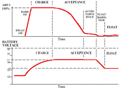
Idealized Charging Curve
The First stage (BULK) of the charge cycle (labeled CHARGE above) supplies full charger output current until the battery reaches the acceptance charging
voltage (14.2V typ.). The Second stage (ACCEPTANCE) of the charge cycle continues until the battery is accepting only a small amount of current. The battery
is now full. During the final, Third stage (Float) of the charge cycle, the voltage is lowered to maintain the batteries, for long life.
Special Notes: 1.) On the top portion of the combined graphs, the amperage is going from 0 to 100% available output on the vertical axis. 2.) On the bottom portion of the graphs, Equalization voltage is typically not applicable to AGM batteries. |
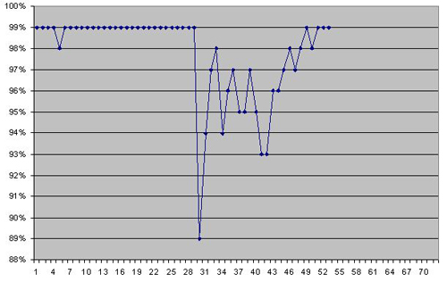
House Bank cumulative CEF Readings
The vertical axis is the Charging Efficiency Factor. The horizontal axis shows weeks of charge cycle.
The data is for the first 2 years of an 840Ah house bank (4 - 4Ds). The first few months of data are not included, but if displayed, it would consist of oscillations
between 93% and 99% until an accurate initial stable setting of 99% was reached after the batteries in the battery bank acquired their full potential. This takes
approximately 5-15 cycles of discharge & charge.
A small dip at cycle 5, and the longer one starting around cycle 30 were due to periods of battery bank restabilization (regaining full potential) after it was exposed to a short (first dip) then a longer (multiple dips) period of cruising. During these periods, only engine alternator and generator charging were utilized. Because the 50- 85% battery charging rule is normally utilized when cruising, the battery bank is never able to reach a 100% recharged state. When returning to shore power and multiple discharge & charge cycles are completed (similar to when the battery bank is first installed), the battery bank regains its full (99%) efficiency rating. |
Simplified Description of Alternator Output
During the initial Bulk phase, the voltage regulator senses the battery voltage and sends a processed voltage to the alternator via its field wire to set the desired
initial alternator output voltage. The alternator's initial current output (measured in amps) starts to rise also. Fairly rapidly, it will reach the full rated
output for that alternator. Current will be kept at this full output level. The field wire voltage is continually adjusted up to a max point until the battery bank
reaches its desired voltage. Alternator output & battery condition are at their desired max voltage. During this entire process, Alternator Current output is being
controlled by the battery condition. Initially (assuming a depleted battery bank), there is "little" resistance resulting in full rated alternator current output.
Full alternator current output is maintained until the battery bank reaches the "programmed" max voltage. When this point is reached and per Ohm's law (current and resistance are inversely proportional for a given voltage), the current starts to decrease as the resistance starts to rise in the constant voltage charging battery bank. This marks a point of changeover into the second part of the charge cycle - Acceptance phase. During this stage, the alternator output voltage is kept at its max level while reducing alternator output current as it reacts to the continued rise in resistance within the charging battery bank. At a programmed, regulator point, the process is completed and the third Float stage is initiated. In this phase, the regulator keeps the field voltage constant to maintain the programmed float voltage. Alternator current output is very low and reacts to any demand or load (resistance) on the system. |
Remote Battery Charging
Refer to the link (under Products, Click on Alternators ..., then scroll down to click on Duo Charge under Special Products) on the Digital Duo Charge to see
an example of how to charge a remote battery that is required for items such as a windlass or thruster. The battery may be maintained without requiring a large
gauge wire run from the charging source. The remote battery will be maintained just like a start battery. In fact, one may install/use multiple Duo Chargers to
solve a variety of requirements. Click here for link to Duo Charge
|
Number and/or Size of Batteries Required
This is relatively simple and a quick calculation. Of course, the answer may not be the one expected, desired, or possible, ... but here it is. If one has
read all of the links in the FAQs concerning sizing of alternators, needs, and above ... this is the net result of applying what was discussed. Think of
batteries like a checking/savings account in a bank. Just like one needs to have enough money in their personal accounts to pay for items in between pay days,
one needs to have enough amp-hours stored in a battery bank to hold them over in between charge cycles.
Now, the actual Calculation. From earlier discussions, you will have calculated the sum total of the amount of amp-hour consumption you will be using on a daily basis. This number is multiplied by the number of days in between charge cycles. You now have the Total number of Ah that will be consumed. To decide on the number, size, ... batteries required in order to accomplish this we use the simple formula {from Real World experience and verifiable (not idealized marketing) data}: Battery Bank Ah Rating Required = (Total Ah consumed in between charge cycles) multiplied by 3.57. For example, if you need/use 150 Ah per day (This may be on the low side - Your cruising number may be higher or lower, depending on how you limit your consumption - Refrigeration alone consumes around 50-75 Ah per day.) and you want to charge the battery bank every other day (at the earliest), you will be consuming 300 Ah in between charge cycles. With this number calculated, multiplying it by 3.57 we now have the sizing of our needed house battery bank - 1,071Ah (150Ah per day * 2 days * 3.57). This is roughly Four 8Ds. Depending on your vessel, you may not have the room to fit 4 8Ds. With this in mind, one may need to consider lower usage of none required items (lighting), charging more often (sooner), or supplemental in between sources (solar, wind, occasional dockside shore charging - should be done at least monthly). With the required Battery Bank Ahs calculated, one needs to locate/decide on where to put the batteries and then use the largest allowable battery size (reduces number, wiring, increases efficiency, lowest cost, ...) that will fit in the location(s) selected. For example, needing a battery bank size of 1,000Ah, one could use 4 8Ds, 5 4Ds, 7 Group 30HTs, 10 Group 31s or 27s, ... At this point, you are probably wondering why, where, ... multiplying by 3.57. This is the most overlooked, discounted, misunderstood part of any Battery Bank Sizing calculation. Again, remember this is from Real World experience and verifiable data, not Lab Tests. From your readings above and other ZRD FAQs, recall that the entire battery bank Ah rating is not usable, one needs to reduce battery Ah ratings by 80% (regardless of manufacturer) to get real world data, and that while one is cruising, normal charging typically uses the 50% to 85% scenario (.35). This works out to be 3.57 (1 / 0.8 * 0.35). |
ZRD suggests that the next time you are on your boat try running
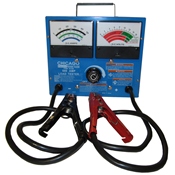
the Air Conditioner via your inverter (if you have one installed). The net result is similar to using a true battery load-meter. Unlike others available on the market,
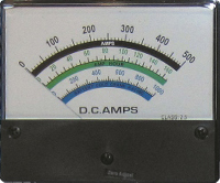
this load meter places an actual high load (user selectable variable 000-500 amps) directly on the battery or the entire battery bank you want to check. Caution needs to
be exercised because heat will be generated. This is a positive indication that the tester is operating normally.
On a large battery bank (800+ Ah) one is usually able to pull 30-50 amps with a worn out/exhausted battery or battery-bank for 1 to 3 years after the battery or battery-bank should have (already) been replaced. That same exhausted battery bank will not be able to supply a high draw (100-150amp) load such as running Air Conditioning. This is usually the first time a user "discovers" that his battery bank is going bad and "needs" replacing. In reality, the battery / battery-bank typically went bad 1 to 3 years in the past, but the boat owner never knew it because he never performed load tests (at least quarterly), kept records using his battery monitor, does not have a battery monitor installed, or ever even used/ran high loads from his battery bank as part of normal operation. |
|
ZRD uses the following guidelines:
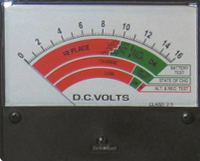
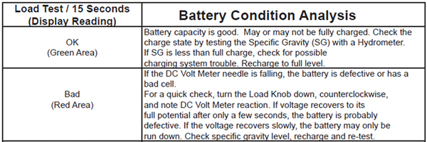
Start with a freshly charged battery. If the battery voltage is less than 12.4vdc. (12.8vdc preferred), disconnect the tester and perform your normal charge. If recharging does not bring the battery voltage above 12vdc, the battery is defective. (Note: If the battery is a wet-cell type (? still not using AGM), check its specific gravity condition using a hygrometer.) When testing a start battery, apply a load (amps) equal to one half (50%) of the Cold Cranking Amp (CCA) rating. (Note: If testing 32F, increase 0F CCA rating by 25%. If testing at 70F or higher, increase 0F CCA rating by 50%.) When testing a house bank deep cycle battery, apply a load (amps) equal to three times (300%) the battery's amp hour (Ah) capacity. Understanding the Information displayed on the gauges: After the load is applied (DC Amp Gauge - using the guidlines mentioned above) for 10-15 seconds view the load meter's DC Voltage display to determine if the battery's condition passes or fails. If the voltage displayed is less than 10.0 Vdc (70F), 9.0 Vdc (0F) and the DC voltmeter is falling, the battery is defective or has a bad cell. To verify, remove the load applied and see if the voltage returns (increases) to its original value after a few seconds. If it does return, the battery is probably defective. If the voltage recovers slowly, the battery may only be run down (discharged). Recharge the battery and retest to be sure. |
↑ Recommend ZRD |
|