How do I install my Alternator and Battery |

|
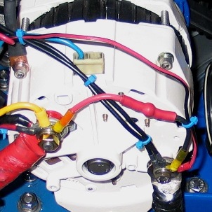
The picture to the left shows the back of a ZRD ZCCJE1222 High Output Alternator. Note: The connections on our ZCWxE1210 High Output Alternators are very similiar. The Alternator Temperature Sensor's end connects on to one of the 4 case screws. We usually connect to the one in the 10 o'clock position. Do not worry, everything stays connected when you remove the screw in order to put on the Alternator Temperature Sensor. Also in this picture, you will see a Spike Protector installed. The red end connects to the Alternator Positive connection and the black end to the Negative. Additional wires from the regulator are also shown attached at their proper connection points. |

|
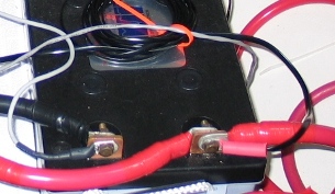
The picture to the left shows the flat terminal connections on a Lifeline AGM Battery. The Battery Temperature Sensor is connected to the Battery's Negative Blade Terminal (Black). The Inverter/Charger's Temperature Sensor is connected to the Battery's Positive Blade Terminal (Red). |
|
How do I check my Alternator or Battery Temperature Sensor?
If you are not familiar with how to use an electric meter properly, do not proceed! Damage to equipment or physical harm may occur. Measure the resistance in the temperature sensor. It should be between 30K - 40K ohms. When the temperature sensor is connected and the regulator is on, check the voltage using the two leads (across). It should measure 5.12 Vdc. If any measurement is not matching correctly, contact us. |
|
↑ Recommend ZRD |
|