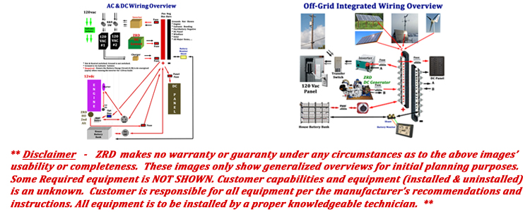
The DC portion of the schematic should show the relationships between all DC sources (house battery bank, starting battery, primary and secondary alternators), charging equipment, DC panels, main electric draw items, bonding system, fusing, bus bars, ... The list is extensive and covers many different scenarios. Schematics need to be tailored to the specific configuration. This ensures clarity and prevents confusion. Otherwise, a schematic would need to be very large in size in order to cover every possibility. This would mean that the schematic would have items included that are not installed or appropriate for a given vessel, regardless of size.
The AC portion of the schematic should show the relationships between all AC sources, (shore power, genset, inverter, ..), selection mechanism(s) (manual, automatic, ...), and galvanic isolation equipment.
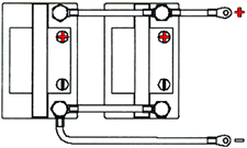
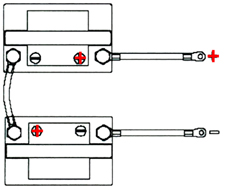
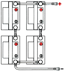
As discussed above, ZRD will design schematics for our customers as needed. They are tailored to their specific installations. Below is a simple overview for wiring up multiple Batteries in 3 configurations. Pay special attention to which Negative terminal is chosen to have the Main Negative Cable connected to. It is NOT the FIRST battery like the Main Positive Cable. It is at the END of the group.
 |
 |
 |
|
• Batteries connected in Parallel
• Each Battery 12vdc, 255ah • Voltage stays the same (12vdc) • Capacity (amps) increases (255 + 255 = 510ah) |
• Batteries connected in Series
• Each Battery 6vdc, 400ah • Voltage gets added for total amount (6 + 6 = 12vdc) • Capacity (amps) stays the same (400ah) |
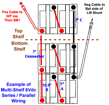
• Batteries connected in Series and Parallel
• Each Battery 6vdc, 400ah • First, Voltage gets added for each bank in series (6 + 6 = 12vdc) X 2 banks • Then, Capacity (amps) increases (400 + 400 = 800ah) |
|
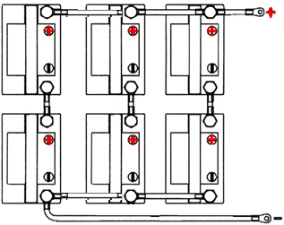
• Properly Wired Large Battery Bank in Series then Parallel
For ANY battery bank of ANY size that includes parallel wiring in any way (vs. only series), one MUST connect the Main Positive and Negative leads to terminals at opposite ends of the battery bank. Too add more batteries in parallel, one would just add them in the middle of the picture with appropriate similar wiring. |
 |
